Worm Gearbox for Solar Tracking Systems
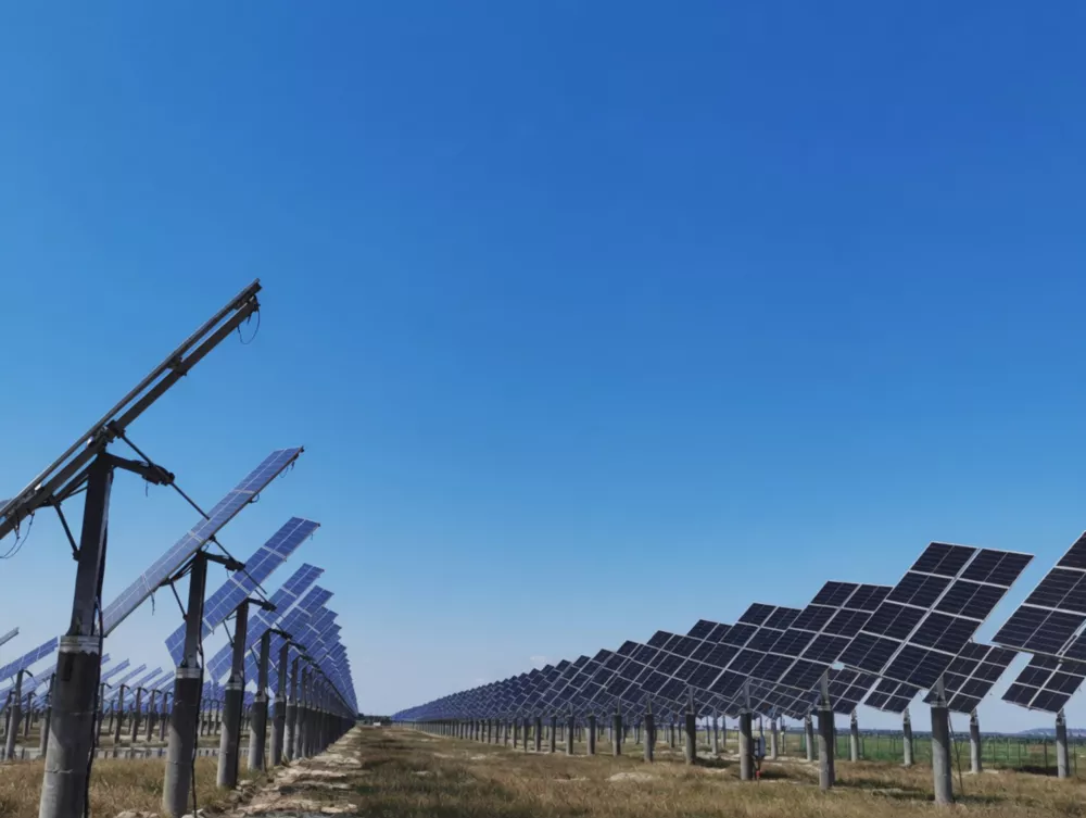
Australia leads the world in solar energy deployment per capita, with rooftop and utility-scale photovoltaic installations across every state and territory. Single-axis and dual-axis solar trackers can increase energy yield by 15–35% compared to fixed-tilt installations. The przekładnia ślimakowa is the established drive mechanism for these trackers, combining the precision rotation needed for accurate solar angle control with the self-locking property that holds panels rigidly in position against wind loads without continuous motor power consumption.
The self-locking characteristic is particularly critical for tracker safety: in high-wind conditions, PV panels present large aerodynamic surfaces that generate significant overturning forces. A gearbox that could back-drive under wind load would require continuous brake or motor current to maintain panel position. The worm reducer’s geometric self-lock provides passive wind resistance at any panel angle position.
Australia’s harsh UV exposure, wide temperature swings from coastal humidity to outback aridity, and the prevalence of solar farms in remote locations with minimal maintenance access all favour the low-maintenance, sealed worm gearbox over alternative drive technologies for tracker applications.
Zastosowania przemysłowe i przypadki użycia
Worm gearboxes serve solar tracking systems in several configurations:
- Single-axis tracker azimuth drive — slow east-west daily rotation of the tracker row structure
- Dual-axis tracker elevation (tilt) drive — north-south seasonal tilt adjustment in addition to azimuth tracking
- Concentrated solar power (CSP) heliostat drives — precision pointing drives for mirror arrays
- Commercial rooftop tracker elevation drive — compact motorised tilt adjustment for commercial roof arrays
- Agri-PV tracker drives — tracker control on agrivoltaic installations over cropping areas
Material specification for solar tracker service: Worm shaft in precision-ground alloy steel — high transmission accuracy is important for solar trackers where pointing error above 0.5° begins to reduce energy yield. Worm wheel in cast phosphor bronze — long service life and low noise critical for residential-adjacent solar farms. Housing in aluminium alloy with UV-stable anodised or powder-coat finish for outdoor service. IP65 mandatory — Australian solar farms experience intense dust storms (particularly inland QLD, SA, and WA) that can rapidly contaminate insufficiently sealed units.
Transmission accuracy: Solar trackers require output shaft accuracy typically in the range ±0.1° to ±0.3° for standard crystalline silicon PV. Worm gearboxes with precision-ground worm profiles achieve backlash of less than 0.1° under load, meeting this requirement in single-stage configurations.
Specyfikacje techniczne i przewodnik wyboru
Skorzystaj z poniższej tabeli, aby wybrać odpowiedni model. Kluczowe parametry to przełożenie, moment obrotowy wyjściowy, wymiary wału i materiał obudowy. Zawsze stosuj właściwe Współczynnik usług (SF) dla Twojego cyklu pracy.
| Parametr | Typowy zakres / wartość | Notatki dotyczące wyboru |
|---|---|---|
| Stosunek | 40:1 – 100:1 typical | Provides 0.2–0.5 RPM output — slow daily panel rotation |
| Moment obrotowy wyjściowy | 50 – 2,500 N·m | Wind load governs; apply SF=1.5 for wind design zone |
| Transmission Accuracy | Backlash < 0.15° under load | Precision ground worm profiles for tracking accuracy |
| Materiał obudowy | Aluminium ADC12, anodised | Lightweight for tracker structure; UV-resistant finish |
| Wał wejściowy | IEC 60034 B14 flange | Direct-mount to compact DC or AC tracker drive motors |
| Smarowanie | Synthetic PAO ISO VG 220 (5-year interval) | Wide temperature range; 25-year design life target |
| Klasa ochrony | IP65 mandatory | Dust storms and blowing sand in inland solar farm locations |
► Współczynnik usług (SF): Obciążenie równomierne SF=1,0 | Umiarkowany wstrząs SF=1,25–1,5 | Silny wstrząs / 24 h ciągły SF=1,75–2,0
► Temperatura otoczenia: Standardowe jednostki o klasie odporności od –10°C do +40°C. W australijskich zakładach o wysokiej temperaturze otoczenia (>45°C) wymagany jest smar wysokotemperaturowy i obniżenie wartości znamionowej temperatury 15%.
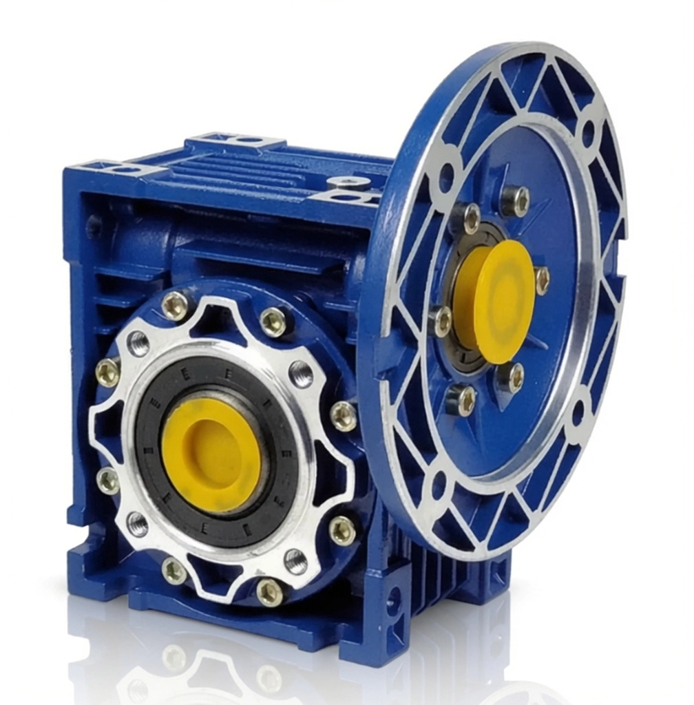
Dostępne w rozmiarach ramy od 025 do 150. Jednostopniowe przełożenia redukcyjne od 5:1 do 100:1. Moment obrotowy wyjściowy do 4200 N·m. Obudowa z aluminium lub żeliwa sferoidalnego. Kołnierz silnika IEC B5/B14. Standard IP65, opcjonalnie IP66/IP67. Smarowanie olejem syntetycznym lub mineralnym.
Standardy zgodności i jakości
Certyfikowany system zarządzania jakością. Każda jednostka produkowana i kontrolowana zgodnie z udokumentowanym systemem zarządzania jakością (QMS) z pełną identyfikowalnością.
Oznaczenie CE zgodne z Dyrektywą Maszynową UE. Szeroko akceptowane w projektach inżynieryjnych w Australii i Nowej Zelandii.
Wymiary kołnierza i wału zgodne z normą IEC. Kompatybilność z montażem bezpośrednim wszystkich głównych marek silników.
Pyłoszczelność i odporność na strumienie wody pod wysokim ciśnieniem. Standard dla instalacji zewnętrznych w Australii.
Studia przypadków
Case Study 1 — Utility-Scale Solar Farm, Broken Hill NSW
Single-Axis PV Tracker Row Drive
Problem klienta: A 50 MW solar farm near Broken Hill was experiencing tracker row gearbox failures linked to dust ingress — the inland NSW location experiences frequent red dust storms with particles measuring 10–50 microns. Standard IP54 gearboxes were allowing fine particle ingress through worn shaft seals after approximately 18 months.
Rozwiązanie: NMRV series worm gearboxes (ratio 80:1, aluminium housing, IP65 with upgraded labyrinth outer seal, synthetic PAO ISO VG 220, UV-stable anodised housing) were installed across all 420 tracker row drives.
Wynik: Zero dust-ingress failures in 30 months of post-installation monitoring (through two major dust storm events). Gearbox oil inspection at 24 months showed no particle contamination in any of the 42 sampled units.
Case Study 2 — Agrivoltaic Solar Array, Swan Hill VIC
Dual-Axis PV Tracker Elevation Drive
Problem klienta: An agrivoltaic installation in Victoria’s Murray Valley required tracker elevation adjustment capability for both solar optimisation and crop shading management. Continuous motor braking was consuming 8% of the array’s energy output.
Rozwiązanie: NMRV-063 worm gearboxes (ratio 100:1, aluminium, IP65, synthetic lubricant) replaced the helical-bevel units on the elevation drive. The 100:1 ratio self-lock eliminated all motor braking requirements.
Wynik: Annual array net output increased by approximately 7.5%. The agrivoltaic operator reported the most significant single improvement in farm energy economics since commissioning.
Case Study 3 — Commercial Rooftop Solar, Brisbane QLD
Rooftop PV Tracker Tilt Adjustment Drive
Problem klienta: A large commercial building in Brisbane was operating a 200 kW rooftop tracker system with motorised seasonal tilt adjustment. The original drive motors were fitted with electromagnetic brakes that were generating heat affecting the motors’ thermal protection relay, causing nuisance trips during summer.
Rozwiązanie: NMRV-040 worm gearboxes (ratio 60:1, compact aluminium, IP65) were installed on all 12 tracker tilt drives. The worm self-lock replaced the electromagnetic brakes entirely.
Wynik: Nuisance thermal trips eliminated. Roof structure load reduced by 12% through motor downsizing. Annual tracker maintenance time reduced by approximately 60%.
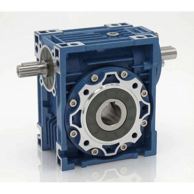
Przekładnie ślimakowe serii NMRV/NRV — rozmiary ramy od 025 do 150, produkowane zgodnie z normą ISO 9001:2015
Dlaczego warto nas wybrać?
Ponad 20 lat produkcji
Produkcja z certyfikatem ISO od 2003 roku. Przekładnie ślimakowe wysyłane do ponad 60 krajów.
Zdalna pomoc techniczna
Diagnostyka za pomocą połączeń wideo w różnych strefach czasowych Australii. Szybka reakcja bez konieczności wizyty na miejscu.
Personalizacja OEM/ODM
Wały niestandardowe, otwory przelotowe, kołnierze niestandardowe i przełożenia. Dostępny pełny przegląd rysunków.
Wartość bezpośrednio od producenta
Brak marży dystrybutora. Przejrzyste ceny hurtowe i znaczne oszczędności przy powtarzających się zamówieniach.
Często zadawane pytania
Get Solar Tracker Drive Sizing and Specification Support
Nasi inżynierowie są gotowi polecić właściwy model przekładni ślimakowej, przełożenie, konfigurację wału i sposób montażu dla Twojego zastosowania.
Dowiedz się więcej na temat strona aplikacji lub dowiedz się o nas na strona o nas.