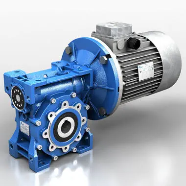
Product Description
Product Parameters
Editing and broadcasting of main materials
1. Body, die-casting aluminum alloy;
2. Worm shaft, 20 Crq steel, high temperature treatment;
3. Worm gear, nickel bronze alloy;
4. Aluminum alloy body, sandblasting and surface anti-corrosion treatment;
5. Cast iron body, painted with bIu RA5571.
Regular center distance specification editing and broadcasting
Center distance: 130 (unit: mm).
Output hole/shaft diameter: 11, 14, 18, 25, 28, 35, 42, 45 (unit: mm)
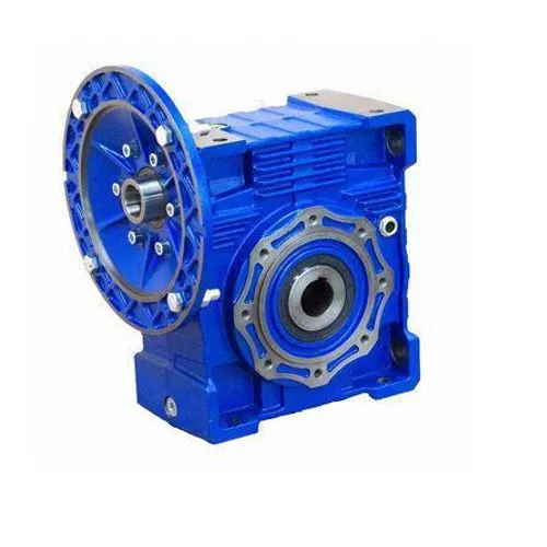
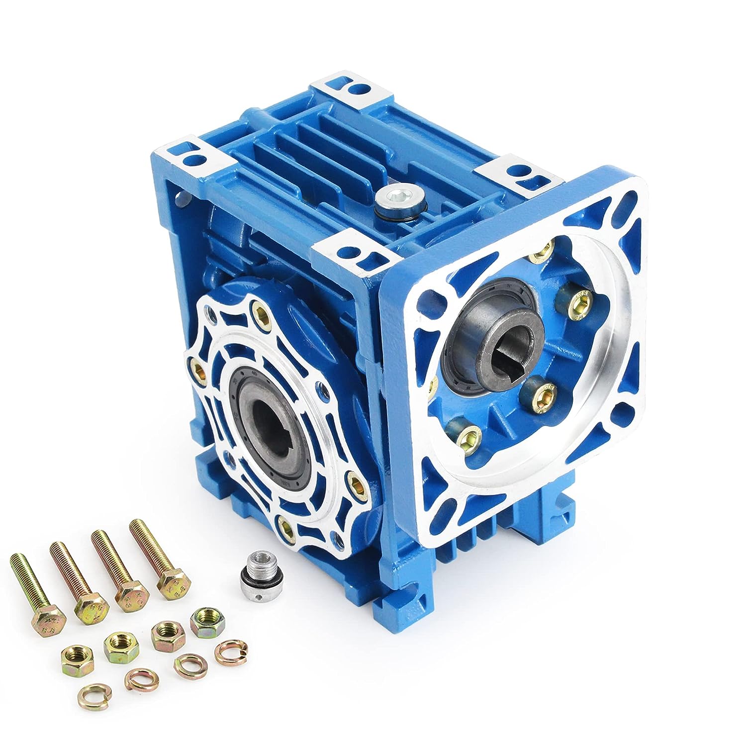
Detailed Photos
|
NMRV-063-30-VS–AS-80B5-0.75KW-B3 |
|||
|
NMRV |
Means hole-input with flange |
||
|
NRV |
Means shaft-input without flange |
||
|
063 |
Centre-to-centre spacing of worm-gear speed reducer |
||
|
30 |
ratio |
||
|
VS |
Double input shaft |
F1(FA) |
Flange putput shaft |
|
AS |
Single output shaft |
AB |
Double output shaft |
|
PAM |
|
80B5 |
Motor mounting facility |
|
0.75KW |
|
B3 |
Mounting position |
|
N2 |
NRV571 |
NRV030 |
NRV040 |
NRV050 |
NRV063 |
NRV075 |
NRV090 |
NRV110 |
NRV130 |
|
400 |
390 |
530 |
1571 |
1400 |
1830 |
2160 |
2390 |
3571 |
3950 |
|
250 |
460 |
620 |
1200 |
1650 |
2150 |
2520 |
2800 |
3530 |
4610 |
|
150 |
550 |
740 |
1420 |
1960 |
2450 |
2990 |
3310 |
4180 |
5470 |
|
100 |
630 |
850 |
1620 |
2250 |
2910 |
3430 |
3800 |
4790 |
6260 |
|
60 |
740 |
1000 |
1920 |
2660 |
3450 |
4060 |
4500 |
5680 |
7420 |
|
40 |
850 |
1150 |
2200 |
3050 |
3950 |
4650 |
5150 |
6500 |
8500 |
|
25 |
990 |
1350 |
2570 |
3570 |
4620 |
5440 |
6571 |
7600 |
9940 |
|
10 |
1350 |
1830 |
3490 |
4840 |
6270 |
7380 |
8180 |
10320 |
13500 |
|
|
|
|
|
|
|
|
|
|
|
|
A |
50 |
65 |
84 |
101 |
120 |
131 |
162 |
191 |
203 |
|
B |
38 |
50 |
64 |
76 |
95 |
101 |
122 |
151 |
163 |
Use and safety guarantee
1. Please check and confirm the matching intensity between worm gear reducer and mechanical equipment before use to assure that it is in the safety range of worm gear reducer performance parameters
2. Worm gear reducer has filled with WA460 lubricating oil. Please replace the lubricating oil after the first starting of 400 hours and after then 4000 hours for lubricating oil replacing cycle
3. There should be enough lubrication in worm gear box and keep regular check with the oil level.
4. When installation. please be careful to avoid sharp instruments bruising the oil seals on output shaft to cause leakage
5. Please confirm the rotation direction before mechanical connection. If the rotation direction is not correct, it will possible injury or damage the devices
6. Please set safety covers in rotating position to avoid of injuring
7. Please pay full attention: it is very dangerous if there is off or falling when movin
| Hardness: | Hardened Tooth Surface |
|---|---|
| Installation: | 90 Degree |
| Layout: | Expansion |
| Gear Shape: | Bevel Gear |
| Step: | Single-Step |
| Type: | Gear Reducer |
| Samples: |
US$ 30/Piece
1 Piece(Min.Order) | |
|---|
Calculating Torque Requirements for an NMRV Gearbox
Calculating torque requirements for an NMRV gearbox involves several steps: Identify Input Torque, Calculate Output Torque, Consider Efficiency, and Add Safety Margin.
- Identify Input Torque: Determine the input torque required by the application, taking into account factors such as load, speed, and efficiency.
- Calculate Output Torque: Use the gear ratio of the NMRV gearbox to calculate the output torque needed to achieve the desired output speed.
- Consider Efficiency: Take into account the efficiency of the NMRV gearbox. The actual output torque will be influenced by the gearbox’s mechanical efficiency.
- Add Safety Margin: To ensure reliable performance and account for variations in operating conditions, it’s recommended to add a safety margin to the calculated torque requirements.
Formula to calculate output torque: Output Torque = Input Torque × Gear Ratio × Gearbox Efficiency
Keep in mind that torque requirements can vary based on the specific application and factors such as load type, duty cycle, and environmental conditions. Consulting with gearbox manufacturers or engineering experts can help ensure accurate torque calculations for your NMRV gearbox application.
Design Principles of an NMRV Gearbox
The design of an NMRV (worm gear) gearbox is based on key principles that enable its efficient and reliable operation:
- Worm Gear Mechanism: The core of an NMRV gearbox is the worm screw and worm wheel. The worm screw, typically cylindrical in shape, meshes with the teeth of the worm wheel. This configuration provides high gear reduction ratios.
- Helical Gearing: The worm screw is usually helical, allowing for smoother engagement with the worm wheel. Helical gearing reduces the sliding friction and noise associated with traditional straight-cut worm gears.
- Compact Design: NMRV gearboxes are designed to be compact, often with a right-angle configuration. This allows for efficient use of space in various applications.
- Alloy Construction: Many NMRV gearboxes are constructed from high-quality alloys, providing durability and corrosion resistance. The choice of materials ensures a gearbox capable of withstanding varying loads and environmental conditions.
- Bearing Support: Bearings support the rotating elements within the gearbox, reducing friction and ensuring smooth operation. Bearings are strategically placed to handle radial and axial loads.
- Sealing and Lubrication: NMRV gearboxes are equipped with effective sealing mechanisms to prevent the entry of contaminants and to retain lubricating oil. Proper lubrication is essential for reducing wear and enhancing gearbox efficiency.
- Efficient Power Transmission: The worm gear mechanism in NMRV gearboxes provides high gear reduction ratios, allowing for efficient power transmission while minimizing energy losses.
- Quiet Operation: The helical design of the worm screw and worm wheel contributes to quieter operation compared to traditional straight-cut worm gears.
- Wide Range of Ratios: NMRV gearboxes are available in various gear ratios, allowing users to select the appropriate configuration for their specific application needs.
The combination of these design principles results in an NMRV gearbox that offers efficient, reliable, and quiet power transmission for a wide range of industrial applications.
Key Features of an NMRV Gearbox
NMRV gearboxes, also known as worm gear reducers, offer several key features that make them suitable for various applications:
- Compact Design: NMRV gearboxes are known for their compact and space-saving design, making them ideal for installations with limited space.
- High Efficiency: These gearboxes offer relatively high efficiency levels, which ensures efficient power transmission and reduced energy loss.
- Speed Reduction: NMRV gearboxes are primarily used for speed reduction applications, where the input speed is reduced while torque is increased.
- Torque Multiplication: The worm and worm wheel mechanism allows for torque multiplication, making NMRV gearboxes suitable for applications requiring high torque output.
- Self-Locking: The helical design of the worm causes self-locking, preventing the output shaft from back-driving the input shaft and providing mechanical locking.
- Smooth Operation: NMRV gearboxes offer smooth and quiet operation, making them suitable for applications where noise reduction is important.
- Wide Range of Ratios: These gearboxes come in a wide range of gear ratios, allowing users to select the appropriate ratio for their specific application.
- Low Maintenance: The simple design and few moving parts contribute to the low maintenance requirements of NMRV gearboxes.
- Versatility: NMRV gearboxes are versatile and can be used in various industries and applications, including conveyor systems, food processing, packaging, and more.
It’s important to consider these key features when selecting an NMRV gearbox for your specific application to ensure optimal performance and efficiency.


editor by CX 2023-12-15


