Worm Gear Drive for Screw Feeders
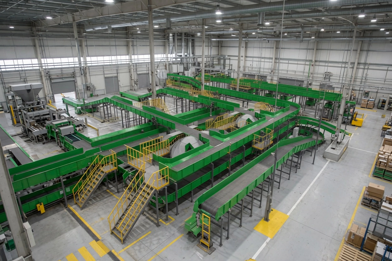
Screw feeders transfer bulk material from a hopper or silo outlet to the next process stage at a controlled volumetric rate. The drive unit must deliver stable, low-speed torque continuously, accommodate the variable resistance as material compacts and arches in the hopper throat, and maintain set speed without hunting. The Schneckengetriebe is the industry-standard drive for screw feeders due to its compact single-stage high reduction, right-angle output, and ability to maintain exact output speed under variable load without electronic correction.
In Australian mining, cement, and chemical processing, screw feeders handling fine abrasive powders — iron ore fines, cement raw meal, fly ash, lime — require drive units completely sealed against ingress. The worm gearbox’s low-profile sealed housing and standard IP65 protection make it the correct choice for dusty material handling environments.
The compact form factor of worm gearboxes — with output shafts available in solid and hollow bore configurations — adapts directly to the screw feeder’s central tube structure, enabling shaft-through mounting without external couplings that could become packed with process material.
Branchenanwendungen und Anwendungsfälle
Worm gear drives appear throughout the screw feeder circuit in processing plants:
- Silo and hopper discharge screw feeders — constant low-speed material extraction against variable head pressure
- Loss-in-weight feeder drive — precise rate control for batching and dosing operations
- Twin-screw mixer drive — coordinated rotation of two screws at matched speeds
- Inclined screw elevator — upward material transfer at angles to 45°; self-lock prevents material rollback
- Rotary valve (airlock) drive — slow precision rotation of rotor between pressure zones
Material specification for screw feeder service: Worm shaft in carbon steel with surface hardening and precision-ground helical thread. Worm wheel in cast phosphor bronze — critical for the sustained sliding contact typical of screw feeder operation. Housing in grey cast iron with heat dissipation fins. Sealed input and output penetrations to IP65.
Selection principle: Screw feeder drives are classified as uniform-load continuous duty (SF=1.0 for standard; SF=1.25 for feeders handling material that may compact). Output speed is typically 2–20 RPM for volumetric feeders and 20–80 RPM for transfer screws.
Technische Spezifikationen & Auswahlhilfe
Nutzen Sie die untenstehende Tabelle, um das passende Modell zu ermitteln. Wichtige Parameter sind Untersetzungsverhältnis, Abtriebsdrehmoment, Wellenabmessungen und Gehäusematerial. Verwenden Sie stets das richtige Modell. Servicefaktor (SF) für Ihren Arbeitszyklus.
| Parameter | Typischer Bereich / Wert | Auswahlhinweise |
|---|---|---|
| Verhältnis | 20:1 – 100:1 | Covers output speeds 14–70 RPM at 1,400 RPM motor input |
| Ausgangsdrehmoment | 10 – 4,200 N·m | Frame 025–150; confirm SF before frame selection |
| Eingangswelle | IEC 60034 B5/B14 flange | Direct-mount to 4-pole standard motors |
| Abtriebswelle | Solid or hollow bore | Hollow bore enables direct screw shaft pass-through |
| Gehäusematerial | Grey Iron with fin casting | Thermal management for continuous low-speed operation |
| Schmierung | Oil bath, standard mineral ISO VG 220 | Synthetic PAO for 24-hour continuous duty |
| Schutzklasse | IP65 standard | Critical for fine powder and dust environments |
► Servicefaktor (SF): Gleichmäßige Belastung SF=1,0 | Mittlerer Stoß SF=1,25–1,5 | Starker Stoß / 24 h Dauerbelastung SF=1,75–2,0
► Umgebungstemperatur: Standardgeräte sind für einen Temperaturbereich von –10 °C bis +40 °C ausgelegt. Für Standorte mit hohen Umgebungstemperaturen in Australien (>45 °C) sind Hochtemperaturschmierstoffe und eine thermische Leistungsreduzierung gemäß 15% erforderlich.
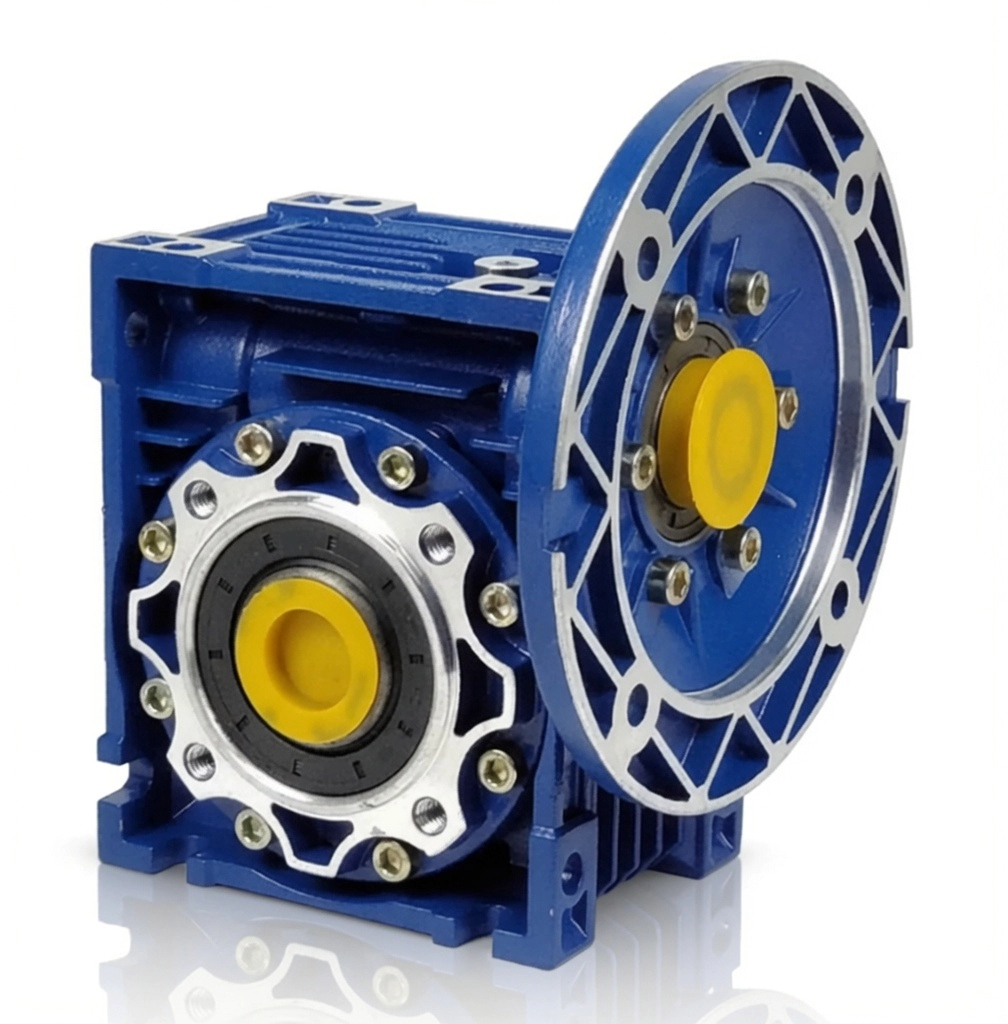
Erhältlich in den Baugrößen 025 bis 150. Einstufige Untersetzungsverhältnisse 5:1 bis 100:1. Abtriebsdrehmoment bis zu 4.200 Nm. Gehäuse aus Aluminium oder Sphäroguss. Motorflansch nach IEC B5/B14. Schutzart IP65 (Standard), IP66/IP67 optional. Schmierung mit synthetischem oder Mineralöl.
Konformitäts- und Qualitätsstandards
Qualitätsmanagementsystem zertifiziert. Jede Einheit wird gemäß einem dokumentierten Qualitätsmanagementsystem mit vollständiger Rückverfolgbarkeit hergestellt und geprüft.
CE-Kennzeichnung gemäß EU-Maschinenrichtlinie. Weitgehend akzeptiert bei australischen und neuseeländischen Maschinenbauprojekten.
IEC-Standard-Flansch- und Wellenabmessungen. Direktmontagekompatibilität mit allen gängigen Motormarken.
Staubdicht und beständig gegen Hochdruckstrahlwasser. Der Standard für australische Außeninstallationen.
Fallstudien
Case Study 1 — Cement Raw Mill Screw Feeder, Victoria
Limestone Silo Discharge Screw Feeder
Problem des Kunden: A cement plant’s limestone silo screw feeder was overheating during the 22-hour daily operating cycle — housing temperature reaching 92°C and tripping the motor protection relay at hour 18 of each shift.
Lösung: Upgraded from an undersized NMRV-063 to NMRV-090 (same ratio 40:1) with synthetic PAO ISO VG 320. The larger frame reduced equilibrium operating temperature by 18°C. A partially clogged outlet adding 35% to running torque was also cleared.
Ergebnis: Housing temperature stabilised at 67°C during the full 22-hour shift with no thermal trips. The synthetic lubricant oil change interval extended to 5,000 hours.
Case Study 2 — Chemical Dosing Screw, Perth WA
Loss-in-Weight Lime Dosing Feeder
Problem des Kunden: A water treatment plant’s lime dosing screw feeder was producing inconsistent dose rates — gearbox output varying ±4 RPM around the setpoint due to backlash, causing pH control instability in the clarifier circuit.
Lösung: NMRV-040 worm gearbox (ratio 60:1) replaced the helical unit. Worm mesh eliminates backlash at low speeds, reducing speed variation to below ±0.2 RPM at the 8 RPM setpoint.
Ergebnis: Clarifier pH consistency improved from ±0.3 pH to ±0.05 pH. Lime consumption reduced by 7% through more precise dosing.
Case Study 3 — Grain Auger Elevator, Southern Queensland
Inclined Grain Auger (30° inclination)
Problem des Kunden: A grain storage facility’s 30° inclined auger was allowing grain to roll back through the auger flights after each operational stop. A separate backstop ratchet mechanism was jamming on fine grain particles.
Lösung: NMRV-063 worm gearbox (ratio 40:1, IP65, food-grade H1 lubricant) replaced the open helical gearbox and ratchet combination. The worm self-lock prevented any rollback on stop.
Ergebnis: Grain rollback eliminated entirely. The ratchet mechanism and its quarterly maintenance requirement were removed from the site maintenance schedule. The same model was subsequently installed on seven further auger points at the facility.
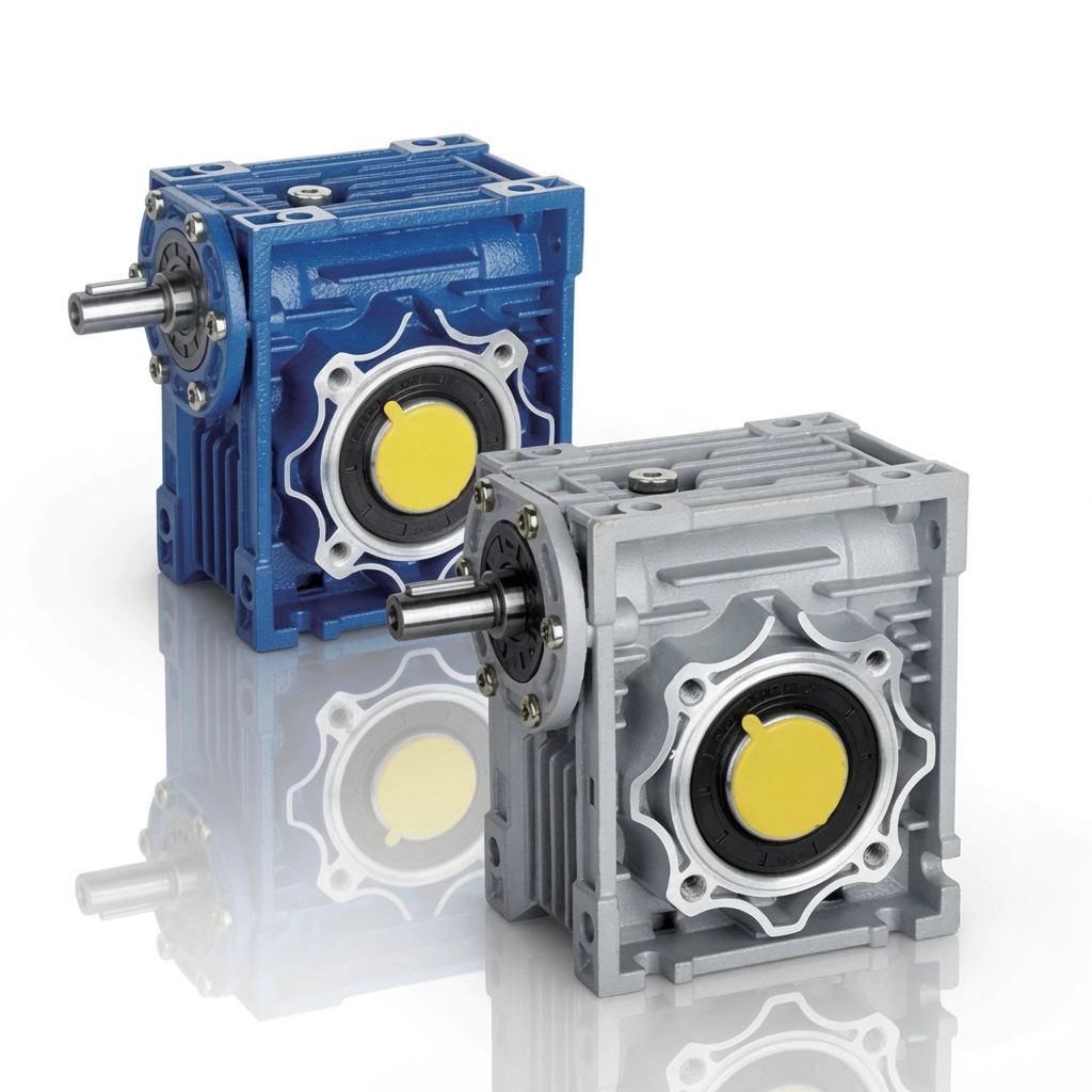
NMRV / NRV Schneckengetriebe – Baugrößen 025 bis 150, hergestellt nach ISO 9001:2015
Warum sollten Sie sich für uns entscheiden?
Über 20 Jahre Erfahrung in der Fertigung
Produktion nach ISO-Norm seit 2003. Schneckengetriebe werden in über 60 Länder geliefert.
Technischer Support per Fernzugriff
Videotelefonische Diagnostik über alle australischen Zeitzonen hinweg. Schnelle Reaktion ohne Vor-Ort-Besuche.
OEM-/ODM-Anpassung
Sonderwellen, Hohlbohrungen, kundenspezifische Flansche und Übersetzungen. Vollständige Zeichnungsprüfung möglich.
Direkt vom Hersteller
Keine Händlermarge. Transparente Mengenpreise mit erheblichen Einsparungen bei Folgebestellungen.
Lagerware & schneller Versand
Standardmäßige NMRV/NRV-Rahmen sind ab Lager verfügbar. Eilbestellungen werden per Expressversand bearbeitet.
Häufig gestellte Fragen
Get Free Screw Feeder Drive Sizing Assistance
Unsere Ingenieure beraten Sie gerne hinsichtlich des passenden Schneckengetriebemodells, des Übersetzungsverhältnisses, der Wellenkonfiguration und der Montageanordnung für Ihre Anwendung.
Entdecken Sie mehr auf der Anwendungsseite oder erfahren Sie mehr über uns auf der Über uns-Seite.