Worm Gear Drive for Screw Feeders
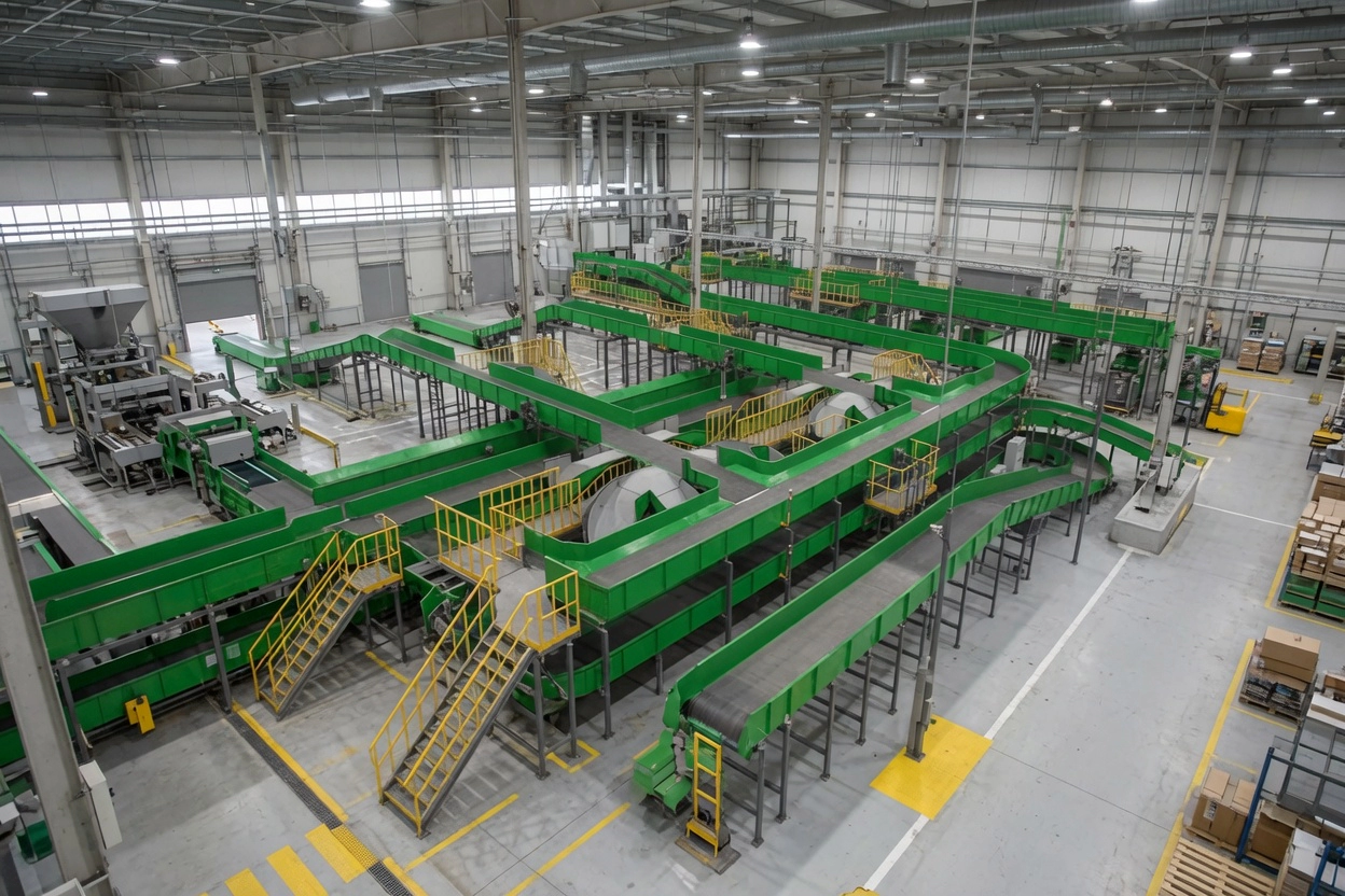
Screw feeders transfer bulk material from a hopper or silo outlet to the next process stage at a controlled volumetric rate. The drive unit must deliver stable, low-speed torque continuously, accommodate the variable resistance as material compacts and arches in the hopper throat, and maintain set speed without hunting. The worm gear drive is the industry-standard drive for screw feeders due to its compact single-stage high reduction, right-angle output, and ability to maintain exact output speed under variable load without electronic correction.
In Australian mining, cement, and chemical processing, screw feeders handling fine abrasive powders — iron ore fines, cement raw meal, fly ash, lime — require drive units completely sealed against ingress. The worm gearbox’s low-profile sealed housing and standard IP65 protection make it the correct choice for dusty material handling environments.
The compact form factor of worm gearboxes — with output shafts available in solid and hollow bore configurations — adapts directly to the screw feeder’s central tube structure, enabling shaft-through mounting without external couplings that could become packed with process material.
Zastosowania przemysłowe i przypadki użycia
Worm gear drives appear throughout the screw feeder circuit in processing plants:
- Silo and hopper discharge screw feeders — constant low-speed material extraction against variable head pressure
- Loss-in-weight feeder drive — precise rate control for batching and dosing operations
- Twin-screw mixer drive — coordinated rotation of two screws at matched speeds
- Inclined screw elevator — upward material transfer at angles to 45°; self-lock prevents material rollback
- Rotary valve (airlock) drive — slow precision rotation of rotor between pressure zones
Material specification for screw feeder service: Worm shaft in carbon steel with surface hardening and precision-ground helical thread. Worm wheel in cast phosphor bronze — critical for the sustained sliding contact typical of screw feeder operation. Housing in grey cast iron with heat dissipation fins. Sealed input and output penetrations to IP65.
Selection principle: Screw feeder drives are classified as uniform-load continuous duty (SF=1.0 for standard; SF=1.25 for feeders handling material that may compact). Output speed is typically 2–20 RPM for volumetric feeders and 20–80 RPM for transfer screws.
Specyfikacje techniczne i przewodnik wyboru
Skorzystaj z poniższej tabeli, aby wybrać odpowiedni model. Kluczowe parametry to przełożenie, moment obrotowy wyjściowy, wymiary wału i materiał obudowy. Zawsze stosuj właściwe Współczynnik usług (SF) dla Twojego cyklu pracy.
| Parametr | Typowy zakres / wartość | Notatki dotyczące wyboru |
|---|---|---|
| Stosunek | 20:1 – 100:1 | Covers output speeds 14–70 RPM at 1,400 RPM motor input |
| Moment obrotowy wyjściowy | 10 – 4,200 N·m | Frame 025–150; confirm SF before frame selection |
| Wał wejściowy | IEC 60034 B5/B14 flange | Direct-mount to 4-pole standard motors |
| Output Shaft | Solid or hollow bore | Hollow bore enables direct screw shaft pass-through |
| Materiał obudowy | Grey Iron with fin casting | Thermal management for continuous low-speed operation |
| Smarowanie | Oil bath, standard mineral ISO VG 220 | Synthetic PAO for 24-hour continuous duty |
| Klasa ochrony | Norma IP65 | Critical for fine powder and dust environments |
► Współczynnik usług (SF): Obciążenie równomierne SF=1,0 | Umiarkowany wstrząs SF=1,25–1,5 | Silny wstrząs / 24 h ciągły SF=1,75–2,0
► Temperatura otoczenia: Standardowe jednostki o klasie odporności od –10°C do +40°C. W australijskich zakładach o wysokiej temperaturze otoczenia (>45°C) wymagany jest smar wysokotemperaturowy i obniżenie wartości znamionowej temperatury 15%.
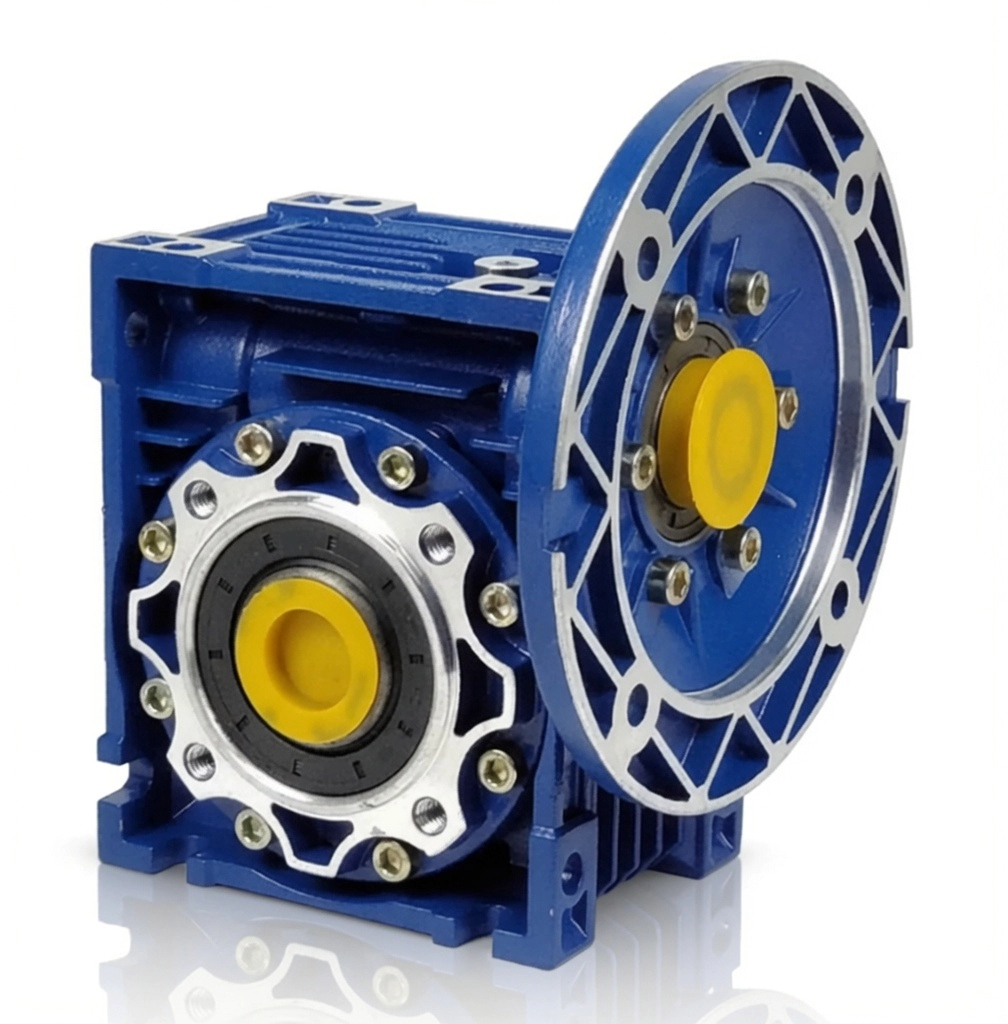
Dostępne w rozmiarach ramy od 025 do 150. Jednostopniowe przełożenia redukcyjne od 5:1 do 100:1. Moment obrotowy wyjściowy do 4200 N·m. Obudowa z aluminium lub żeliwa sferoidalnego. Kołnierz silnika IEC B5/B14. Standard IP65, opcjonalnie IP66/IP67. Smarowanie olejem syntetycznym lub mineralnym.
Standardy zgodności i jakości
Certyfikowany system zarządzania jakością. Każda jednostka produkowana i kontrolowana zgodnie z udokumentowanym systemem zarządzania jakością (QMS) z pełną identyfikowalnością.
Oznaczenie CE zgodne z Dyrektywą Maszynową UE. Szeroko akceptowane w projektach inżynieryjnych w Australii i Nowej Zelandii.
Wymiary kołnierza i wału zgodne z normą IEC. Kompatybilność z montażem bezpośrednim wszystkich głównych marek silników.
Pyłoszczelność i odporność na strumienie wody pod wysokim ciśnieniem. Standard dla instalacji zewnętrznych w Australii.
Studia przypadków
Case Study 1 — Cement Raw Mill Screw Feeder, Victoria
Limestone Silo Discharge Screw Feeder
Problem klienta: A cement plant’s limestone silo screw feeder was overheating during the 22-hour daily operating cycle — housing temperature reaching 92°C and tripping the motor protection relay at hour 18 of each shift.
Rozwiązanie: Upgraded from an undersized NMRV-063 to NMRV-090 (same ratio 40:1) with synthetic PAO ISO VG 320. The larger frame reduced equilibrium operating temperature by 18°C. A partially clogged outlet adding 35% to running torque was also cleared.
Wynik: Housing temperature stabilised at 67°C during the full 22-hour shift with no thermal trips. The synthetic lubricant oil change interval extended to 5,000 hours.
Case Study 2 — Chemical Dosing Screw, Perth WA
Loss-in-Weight Lime Dosing Feeder
Problem klienta: A water treatment plant’s lime dosing screw feeder was producing inconsistent dose rates — gearbox output varying ±4 RPM around the setpoint due to backlash, causing pH control instability in the clarifier circuit.
Rozwiązanie: NMRV-040 worm gearbox (ratio 60:1) replaced the helical unit. Worm mesh eliminates backlash at low speeds, reducing speed variation to below ±0.2 RPM at the 8 RPM setpoint.
Wynik: Clarifier pH consistency improved from ±0.3 pH to ±0.05 pH. Lime consumption reduced by 7% through more precise dosing.
Case Study 3 — Grain Auger Elevator, Southern Queensland
Inclined Grain Auger (30° inclination)
Problem klienta: A grain storage facility’s 30° inclined auger was allowing grain to roll back through the auger flights after each operational stop. A separate backstop ratchet mechanism was jamming on fine grain particles.
Rozwiązanie: NMRV-063 worm gearbox (ratio 40:1, IP65, food-grade H1 lubricant) replaced the open helical gearbox and ratchet combination. The worm self-lock prevented any rollback on stop.
Wynik: Grain rollback eliminated entirely. The ratchet mechanism and its quarterly maintenance requirement were removed from the site maintenance schedule. The same model was subsequently installed on seven further auger points at the facility.
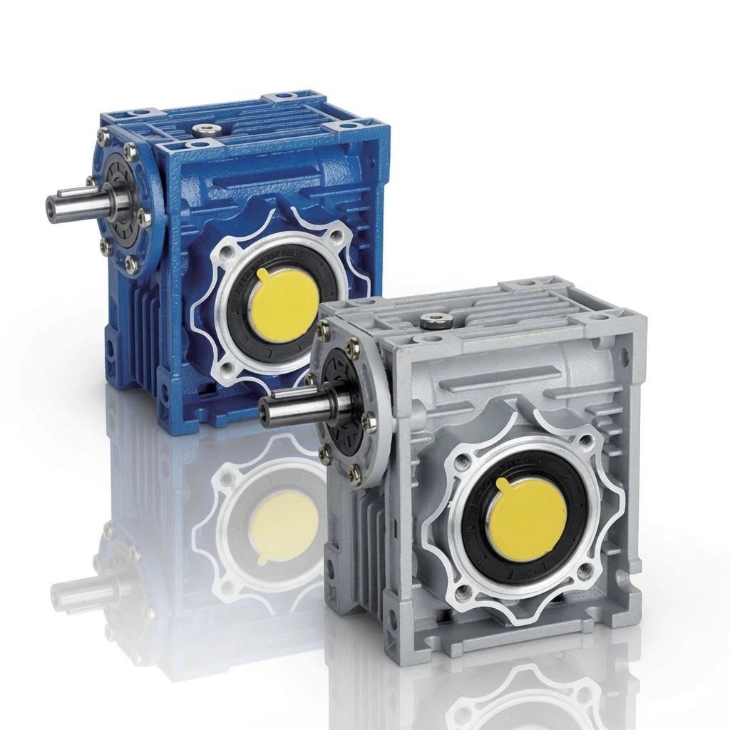
Przekładnie ślimakowe serii NMRV/NRV — rozmiary ramy od 025 do 150, produkowane zgodnie z normą ISO 9001:2015
Dlaczego warto nas wybrać?
Ponad 20 lat produkcji
Produkcja z certyfikatem ISO od 2003 roku. Przekładnie ślimakowe wysyłane do ponad 60 krajów.
Zdalna pomoc techniczna
Diagnostyka za pomocą połączeń wideo w różnych strefach czasowych Australii. Szybka reakcja bez konieczności wizyty na miejscu.
Personalizacja OEM/ODM
Wały niestandardowe, otwory przelotowe, kołnierze niestandardowe i przełożenia. Dostępny pełny przegląd rysunków.
Wartość bezpośrednio od producenta
Brak marży dystrybutora. Przejrzyste ceny hurtowe i znaczne oszczędności przy powtarzających się zamówieniach.
Stan magazynowy i szybka wysyłka
Standardowe ramy NMRV/NRV dostępne w magazynie. Pilne zamówienia realizowane z dostawą ekspresową.
Często zadawane pytania
Get Free Screw Feeder Drive Sizing Assistance
Nasi inżynierowie są gotowi polecić właściwy model przekładni ślimakowej, przełożenie, konfigurację wału i sposób montażu dla Twojego zastosowania.
Dowiedz się więcej na temat strona aplikacji lub dowiedz się o nas na strona o nas.