Worm Gear Reducer for Mining Crushers
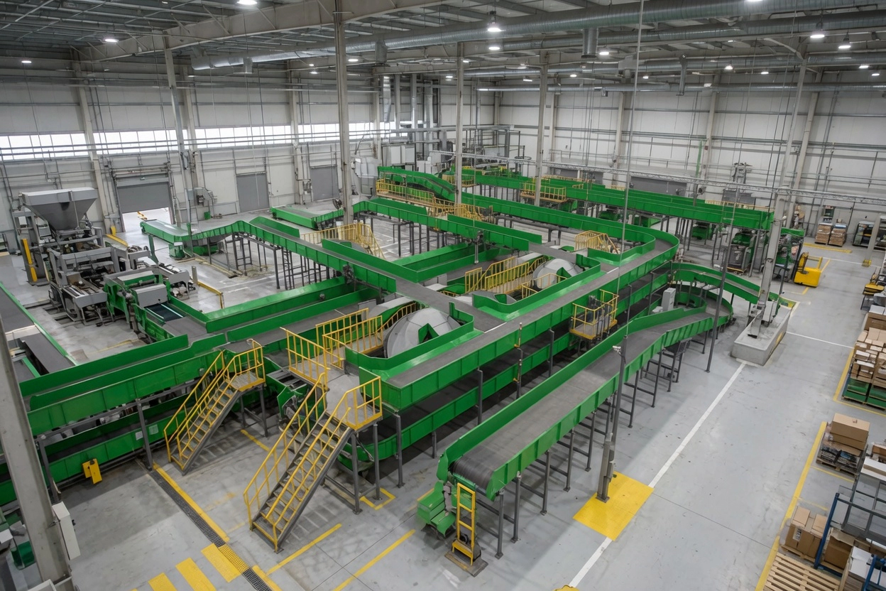
Mining crushers — jaw crushers, cone crushers, and roll crushers — represent some of the most mechanically demanding environments in heavy industry. They impose extreme impact loads, high starting torques, and continuous vibration on every drive component. The Schneckengetriebe deployed in crusher auxiliary and feeder drives delivers high reduction ratios in a compact envelope, ensuring full drive torque from a standard motor frame even in the space-constrained confines of a mine shaft or processing plant.
While the primary crusher drive may use a direct-drive or fluid coupling arrangement, worm gearboxes serve critical roles in the crusher circuit: driving the vibrating grizzly feeder that regulates ore feed rate, actuating the CSS adjustment mechanism, driving the lubrication oil pump motor on large gyratory crushers, and controlling the apron feeder beneath the jaw crusher discharge.
In all these roles, the worm reducer’s defining advantage is torque multiplication at compact size — reduction ratios up to 100:1 from a single stage allow a small motor to overcome the starting inertia and shock loads characteristic of crusher circuits.
Branchenanwendungen und Anwendungsfälle
In a typical crusher plant layout, worm gearboxes appear at multiple points in the circuit:
- Vibrating grizzly feeder drives — eccentric mass adjustment and feed rate control
- CSS adjustment actuators on cone crushers — precise low-speed setting changes under hydraulic load
- Apron feeder drives beneath jaw crushers — high starting torque against loaded apron pans
- Roll crusher drives (secondary stage) — low-speed high-torque direct drive of crushing rolls
- Lubrication pump drives on large gyratory crushers — slow continuous pump rotation
Material specifications for crusher duty: Worm shaft in carburised-and-quenched alloy steel (HRC 60–62). Worm wheel in special alloy bronze with higher tin content for improved impact resistance. Housing in ductile iron GGG40 with IP65 sealing as minimum — IP66 recommended near crusher discharge zones where water-and-fines slurry splashing is common.
Shock load and service factor: Crusher circuits are classified as heavy-shock applications with service factor SF=1.75–2.0. This means the gearbox must be selected with a rated output torque at least 1.75× the calculated application torque. Undersizing a worm gearbox in a crusher circuit leads to premature bronze wheel wear and thermal overload.

Technische Spezifikationen & Auswahlhilfe
Nutzen Sie die untenstehende Tabelle, um das passende Modell zu ermitteln. Wichtige Parameter sind Untersetzungsverhältnis, Abtriebsdrehmoment, Wellenabmessungen und Gehäusematerial. Verwenden Sie stets das richtige Modell. Servicefaktor (SF) für Ihren Arbeitszyklus.
| Parameter | Typischer Bereich / Wert | Auswahlhinweise |
|---|---|---|
| Verhältnis | 20:1 – 100:1 recommended | Higher ratios for very slow feeder or actuator drives |
| Output Torque (SF=1.0) | Up to 4,200 N·m | Apply SF 1.75–2.0 for crusher circuit selection |
| Eingangswelle | IEC B5/B14 flange | IEC 60034 — direct-mount to standard motors |
| Abtriebswelle | 25 – 50 mm solid or hollow bore | Hollow bore recommended for direct roll-crusher shaft coupling |
| Gehäusematerial | Gusseisen mit Kugelgraphit GGG40 | Mandatory for shock-load crusher circuit service |
| Lagertyp | Taper roller (input + output) | Required for combined radial/axial load in crusher duty |
| Schutzklasse | IP65 minimum; IP66 preferred | Near crusher discharge and slurry zones specify IP66 |
► Servicefaktor (SF): Gleichmäßige Belastung SF=1,0 | Mittlerer Stoß SF=1,25–1,5 | Starker Stoß / 24 h Dauerbelastung SF=1,75–2,0
► Umgebungstemperatur: Standardgeräte sind für einen Temperaturbereich von –10 °C bis +40 °C ausgelegt. Für Standorte mit hohen Umgebungstemperaturen in Australien (>45 °C) sind Hochtemperaturschmierstoffe und eine thermische Leistungsreduzierung gemäß 15% erforderlich.
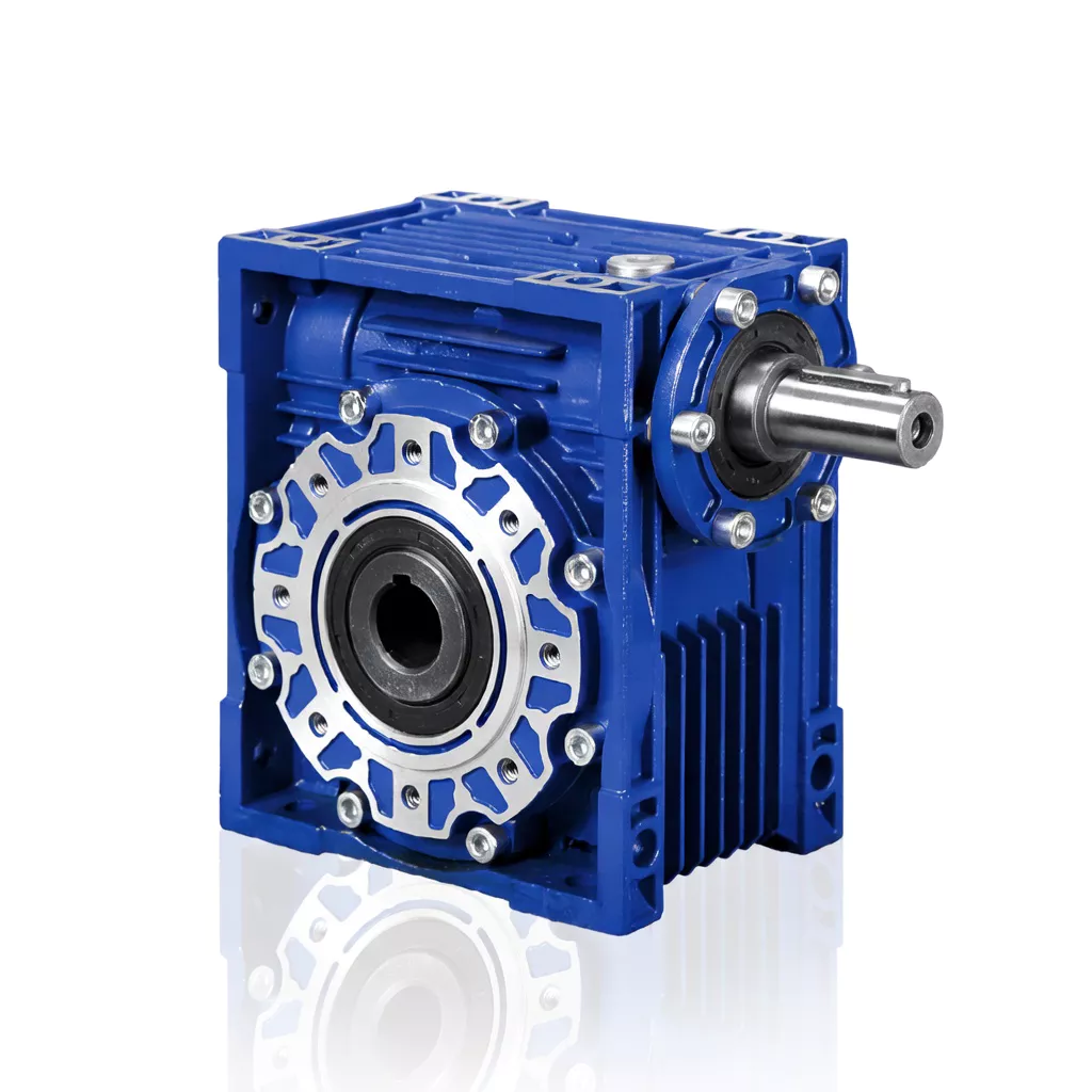
Erhältlich in den Baugrößen 025 bis 150. Einstufige Untersetzungsverhältnisse 5:1 bis 100:1. Abtriebsdrehmoment bis zu 4.200 Nm. Gehäuse aus Aluminium oder Sphäroguss. Motorflansch nach IEC B5/B14. Schutzart IP65 (Standard), IP66/IP67 optional. Schmierung mit synthetischem oder Mineralöl.
Konformitäts- und Qualitätsstandards
Qualitätsmanagementsystem zertifiziert. Jede Einheit wird gemäß einem dokumentierten Qualitätsmanagementsystem mit vollständiger Rückverfolgbarkeit hergestellt und geprüft.
CE-Kennzeichnung gemäß EU-Maschinenrichtlinie. Weitgehend akzeptiert bei australischen und neuseeländischen Maschinenbauprojekten.
IEC-Standard-Flansch- und Wellenabmessungen. Direktmontagekompatibilität mit allen gängigen Motormarken.
Staubdicht und beständig gegen Hochdruckstrahlwasser. Der Standard für australische Außeninstallationen.
Fallstudien
Case Study 1 — Gold Mine Apron Feeder, Kalgoorlie WA
Apron Feeder beneath Primary Jaw Crusher
Problem des Kunden: A Kalgoorlie gold mine experienced monthly worm wheel failures. The original gearbox had been sized at SF=1.0 — adequate for uniform load but unable to handle impact torques when large ore blocks fell onto the apron pans.
Lösung: NRV-130 worm gearbox (ratio 60:1, SF=2.0 selected output torque 2,800 N·m, taper roller bearings, IP66) replaced the undersized unit. A misalignment issue in the apron chain was also corrected.
Ergebnis: Worm wheel life extended from 4–6 weeks to over 18 months. Annual saving approximately $14,000 in parts and labour.
Case Study 2 — Quarry Grizzly Feeder Drive, Blue Mountains NSW
Vibrating Grizzly Feeder
Problem des Kunden: A sandstone quarry’s grizzly feeder drive was producing excessive vibration transmitted through the gearbox housing to the motor frame, causing terminal connection loosening and brush wear on the slip-ring motor.
Lösung: NMRV-110 worm gearbox with anti-vibration mounting feet and flexible coupling between motor and gearbox input shaft. Worm meshing geometry absorbs torsional shock better than helical gears.
Ergebnis: Motor terminal re-tightening interval extended from 4 weeks to 18 months. Slip-ring brush life doubled.
Case Study 3 — CSS Adjustment Actuator, Iron Ore Cone Crusher WA
Cone Crusher CSS Adjustment Drive
Problem des Kunden: The CSS adjustment actuator on a large secondary cone crusher was too fast — operators were overshooting target CSS by up to 5 mm due to inertia in the hydraulic adjustment system.
Lösung: A two-stage tandem NMRV worm gearbox (combined ratio 3,200:1) was installed, giving precise incremental CSS adjustment with positional resolution of 0.2 mm per motor revolution.
Ergebnis: CSS setting accuracy improved to ±0.5 mm. Product size P80 consistency improved by 12%, reducing oversize recirculation by 8% and increasing plant throughput.
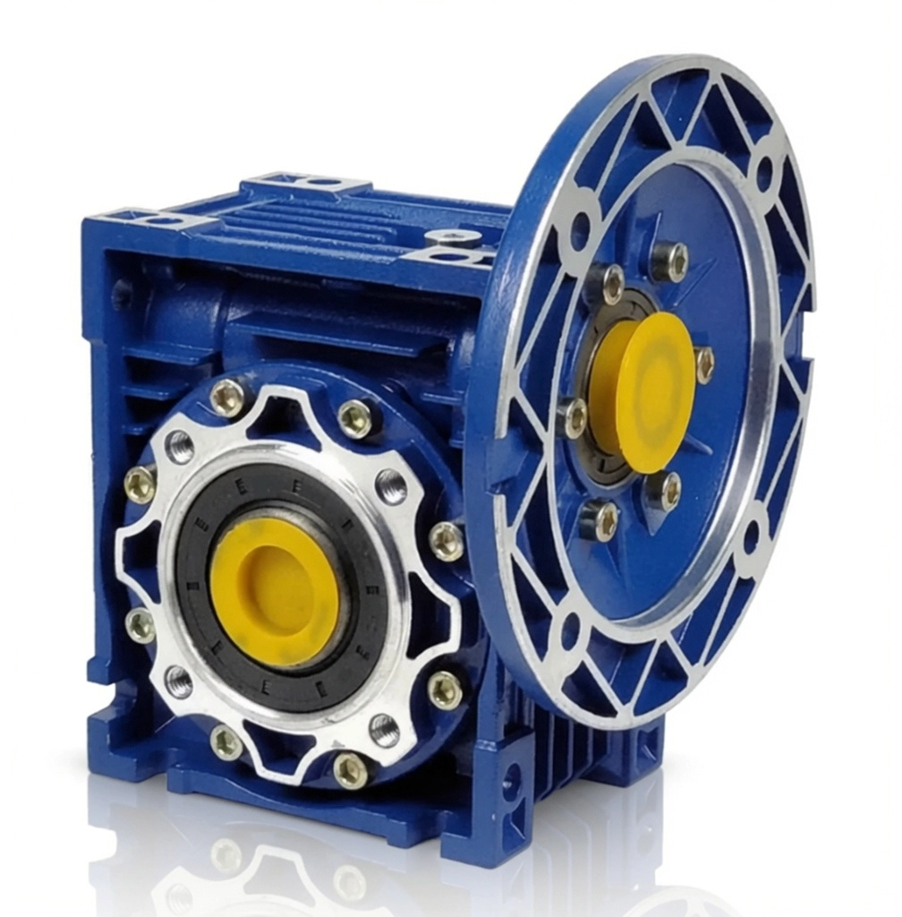
NMRV / NRV Schneckengetriebe – Baugrößen 025 bis 150, hergestellt nach ISO 9001:2015
Warum sollten Sie sich für uns entscheiden?
Über 20 Jahre Erfahrung in der Fertigung
Produktion nach ISO-Norm seit 2003. Schneckengetriebe werden in über 60 Länder geliefert.
Technischer Support per Fernzugriff
Videotelefonische Diagnostik über alle australischen Zeitzonen hinweg. Schnelle Reaktion ohne Vor-Ort-Besuche.
OEM-/ODM-Anpassung
Sonderwellen, Hohlbohrungen, kundenspezifische Flansche und Übersetzungen. Vollständige Zeichnungsprüfung möglich.
Direkt vom Hersteller
Keine Händlermarge. Transparente Mengenpreise mit erheblichen Einsparungen bei Folgebestellungen.
Lagerware & schneller Versand
Standardmäßige NMRV/NRV-Rahmen sind ab Lager verfügbar. Eilbestellungen werden per Expressversand bearbeitet.
Häufig gestellte Fragen
Request Free Crusher Drive Selection and Sizing
Unsere Ingenieure beraten Sie gerne hinsichtlich des passenden Schneckengetriebemodells, des Übersetzungsverhältnisses, der Wellenkonfiguration und der Montageanordnung für Ihre Anwendung.
Entdecken Sie mehr auf der Anwendungsseite oder erfahren Sie mehr über uns auf der Über uns-Seite.