Worm Gear Reducer for Mining Crushers
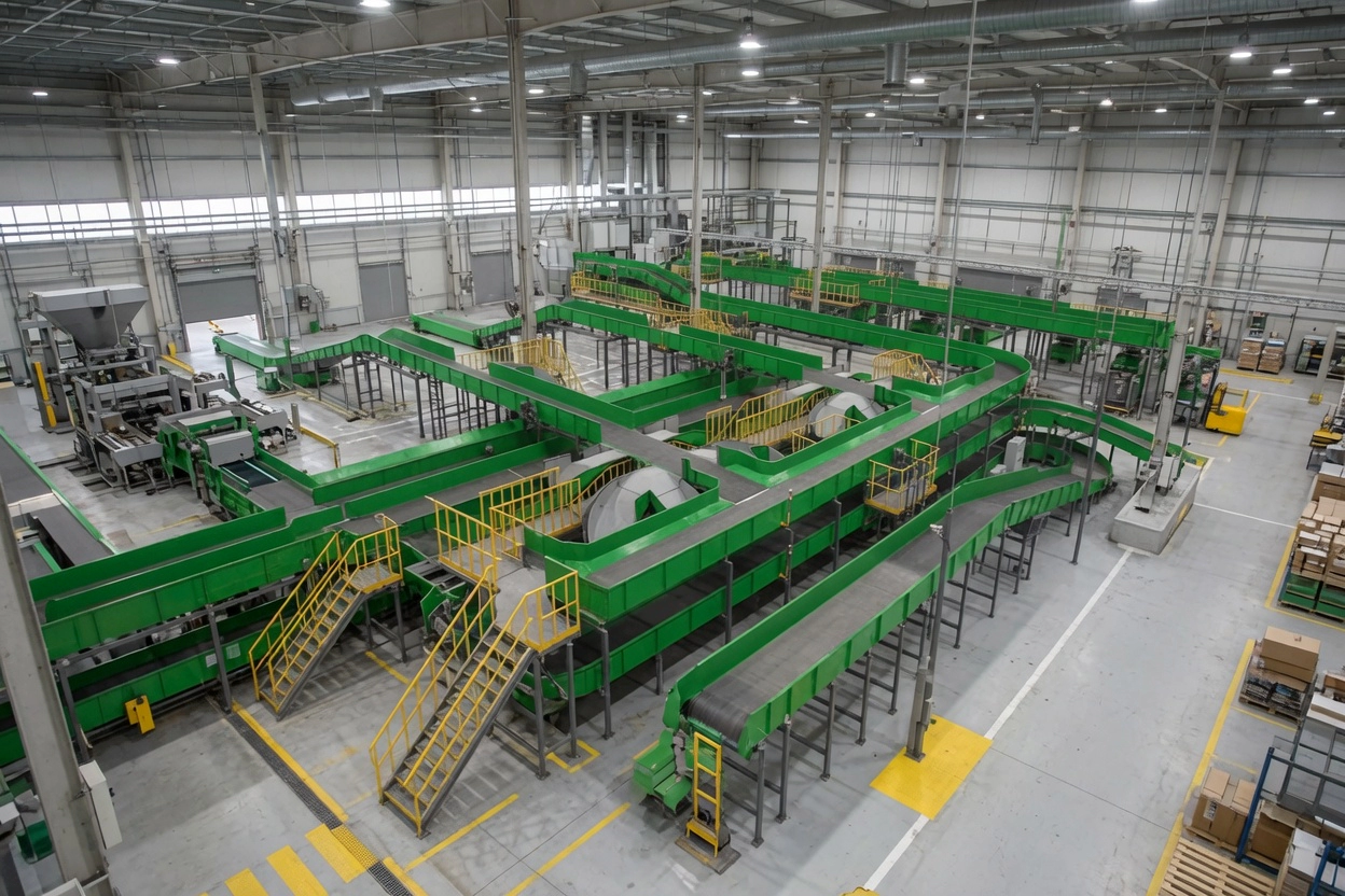
Mining crushers — jaw crushers, cone crushers, and roll crushers — represent some of the most mechanically demanding environments in heavy industry. They impose extreme impact loads, high starting torques, and continuous vibration on every drive component. The réducteur à vis sans fin deployed in crusher auxiliary and feeder drives delivers high reduction ratios in a compact envelope, ensuring full drive torque from a standard motor frame even in the space-constrained confines of a mine shaft or processing plant.
While the primary crusher drive may use a direct-drive or fluid coupling arrangement, worm gearboxes serve critical roles in the crusher circuit: driving the vibrating grizzly feeder that regulates ore feed rate, actuating the CSS adjustment mechanism, driving the lubrication oil pump motor on large gyratory crushers, and controlling the apron feeder beneath the jaw crusher discharge.
In all these roles, the worm reducer’s defining advantage is torque multiplication at compact size — reduction ratios up to 100:1 from a single stage allow a small motor to overcome the starting inertia and shock loads characteristic of crusher circuits.
Applications industrielles et cas d'utilisation
In a typical crusher plant layout, worm gearboxes appear at multiple points in the circuit:
- Vibrating grizzly feeder drives — eccentric mass adjustment and feed rate control
- CSS adjustment actuators on cone crushers — precise low-speed setting changes under hydraulic load
- Apron feeder drives beneath jaw crushers — high starting torque against loaded apron pans
- Roll crusher drives (secondary stage) — low-speed high-torque direct drive of crushing rolls
- Lubrication pump drives on large gyratory crushers — slow continuous pump rotation
Material specifications for crusher duty: Worm shaft in carburised-and-quenched alloy steel (HRC 60–62). Worm wheel in special alloy bronze with higher tin content for improved impact resistance. Housing in ductile iron GGG40 with IP65 sealing as minimum — IP66 recommended near crusher discharge zones where water-and-fines slurry splashing is common.
Shock load and service factor: Crusher circuits are classified as heavy-shock applications with service factor SF=1.75–2.0. This means the gearbox must be selected with a rated output torque at least 1.75× the calculated application torque. Undersizing a worm gearbox in a crusher circuit leads to premature bronze wheel wear and thermal overload.

Spécifications techniques et guide de sélection
Utilisez le tableau ci-dessous pour identifier le modèle approprié. Les paramètres clés comprennent le rapport de réduction, le couple de sortie, les dimensions de l'arbre et le matériau du carter. Appliquez toujours le bon réglage. Facteur de service (SF) pour votre cycle de service.
| Paramètre | Plage/valeur typique | Notes de sélection |
|---|---|---|
| Rapport | 20:1 – 100:1 recommended | Higher ratios for very slow feeder or actuator drives |
| Couple de sortie (SF=1,0) | Up to 4,200 N·m | Apply SF 1.75–2.0 for crusher circuit selection |
| Arbre d'entrée | IEC B5/B14 flange | CEI 60034 — direct-mount to standard motors |
| Arbre de sortie | 25 – 50 mm solid or hollow bore | Hollow bore recommended for direct roll-crusher shaft coupling |
| Matériau du boîtier | Fonte ductile GGG40 | Mandatory for shock-load crusher circuit service |
| Type de roulement | Taper roller (input + output) | Required for combined radial/axial load in crusher duty |
| Classe de protection | IP65 minimum; IP66 preferred | Near crusher discharge and slurry zones specify IP66 |
► Facteur de service (SF) : Charge uniforme SF=1,0 | Choc modéré SF=1,25–1,5 | Choc important / 24 h en continu SF=1,75–2,0
► Température ambiante : Unités standard conçues pour une température ambiante de –10°C à +40°C. Les sites australiens à température ambiante élevée (>45°C) nécessitent un lubrifiant haute température et une réduction de puissance thermique 15%.
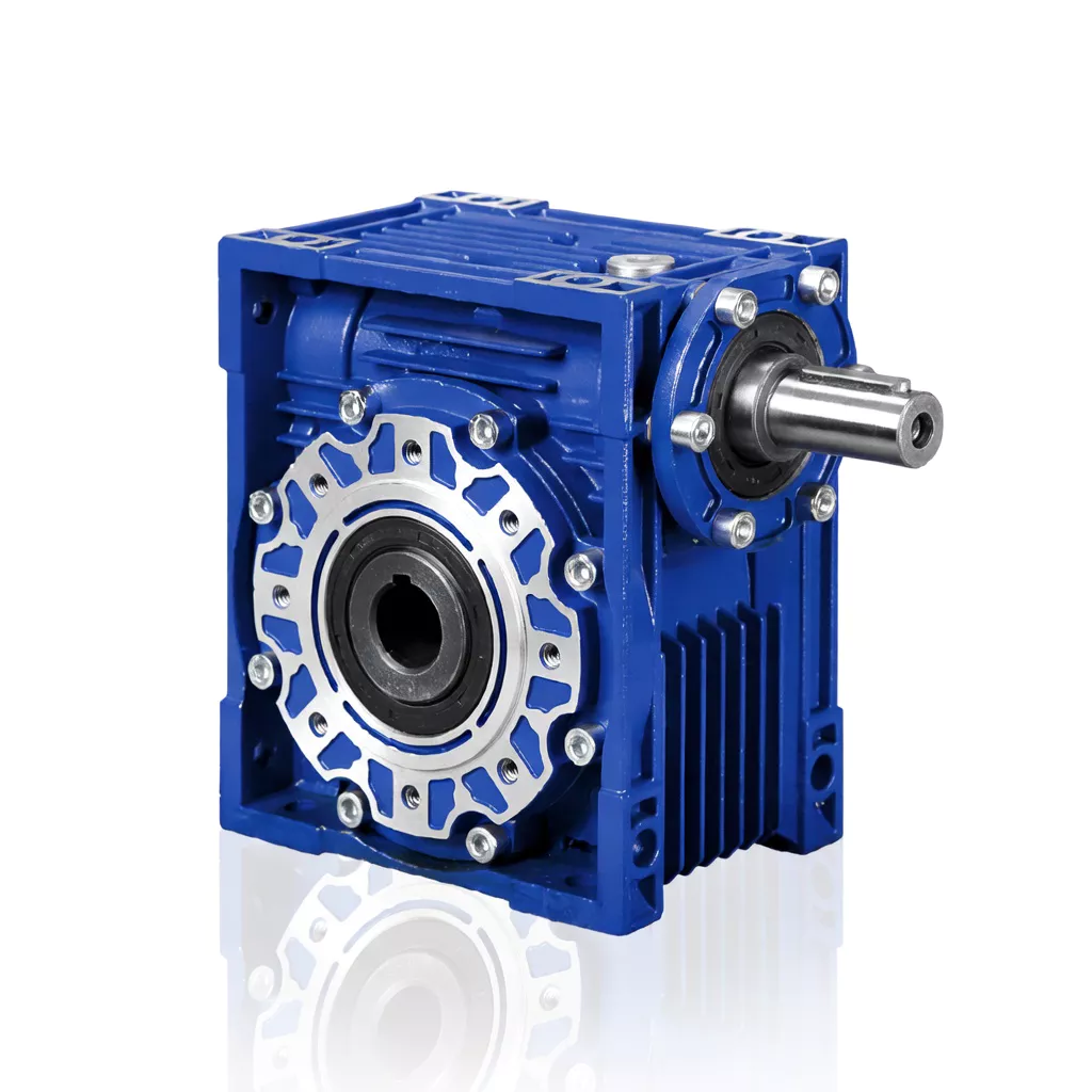
Disponible en tailles de châssis 025 à 150. Rapports de réduction mono-étagés de 5:1 à 100:1. Couple de sortie jusqu'à 4 200 N·m. Carter en aluminium ou en fonte ductile. Bride moteur IEC B5/B14. Indice de protection IP65 de série, IP66/IP67 en option. Lubrification à l'huile synthétique ou minérale.
Normes de conformité et de qualité
Système de gestion de la qualité certifié. Chaque unité est fabriquée et inspectée conformément à un système de gestion de la qualité documenté, avec une traçabilité complète.
Marquage CE conforme à la directive européenne sur les machines. Largement utilisé dans les projets d'ingénierie australiens et néo-zélandais.
Dimensions de la bride et de l'arbre conformes aux normes CEI. Compatibilité à montage direct avec toutes les grandes marques de moteurs.
Étanche à la poussière et résistante aux jets d'eau haute pression. La norme pour les installations extérieures australiennes.
Études de cas
Case Study 1 — Gold Mine Apron Feeder, Kalgoorlie WA
Apron Feeder beneath Primary Jaw Crusher
Point sensible du client : A Kalgoorlie gold mine experienced monthly worm wheel failures. The original gearbox had been sized at SF=1.0 — adequate for uniform load but unable to handle impact torques when large ore blocks fell onto the apron pans.
Solution: NRV-130 worm gearbox (ratio 60:1, SF=2.0 selected output torque 2,800 N·m, taper roller bearings, IP66) replaced the undersized unit. A misalignment issue in the apron chain was also corrected.
Résultat: Worm wheel life extended from 4–6 weeks to over 18 months. Annual saving approximately $14,000 in parts and labour.
Case Study 2 — Quarry Grizzly Feeder Drive, Blue Mountains NSW
Vibrating Grizzly Feeder
Point sensible du client : A sandstone quarry’s grizzly feeder drive was producing excessive vibration transmitted through the gearbox housing to the motor frame, causing terminal connection loosening and brush wear on the slip-ring motor.
Solution: NMRV-110 worm gearbox with anti-vibration mounting feet and flexible coupling between motor and gearbox input shaft. Worm meshing geometry absorbs torsional shock better than helical gears.
Résultat: Motor terminal re-tightening interval extended from 4 weeks to 18 months. Slip-ring brush life doubled.
Case Study 3 — CSS Adjustment Actuator, Iron Ore Cone Crusher WA
Cone Crusher CSS Adjustment Drive
Point sensible du client : The CSS adjustment actuator on a large secondary cone crusher was too fast — operators were overshooting target CSS by up to 5 mm due to inertia in the hydraulic adjustment system.
Solution: A two-stage tandem NMRV worm gearbox (combined ratio 3,200:1) was installed, giving precise incremental CSS adjustment with positional resolution of 0.2 mm per motor revolution.
Résultat: CSS setting accuracy improved to ±0.5 mm. Product size P80 consistency improved by 12%, reducing oversize recirculation by 8% and increasing plant throughput.
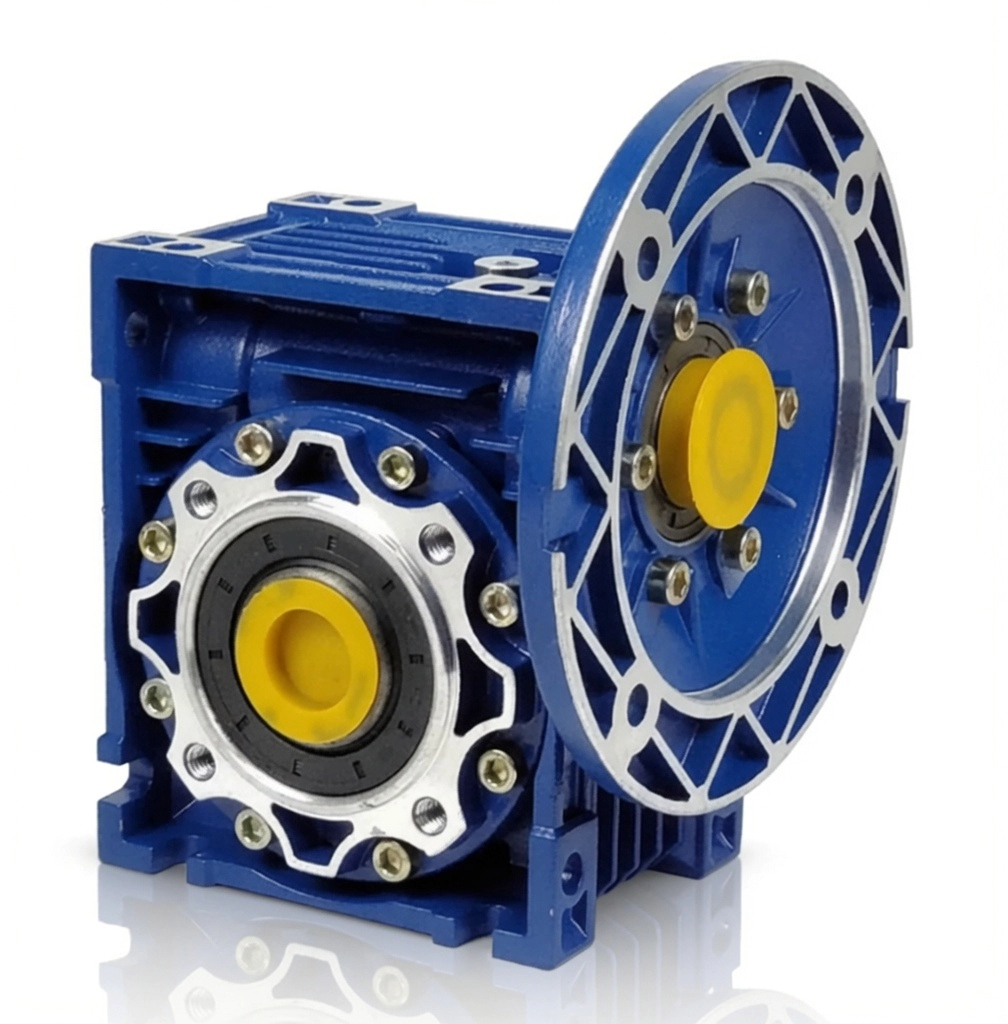
Réducteurs à vis sans fin séries NMRV / NRV — tailles de châssis 025 à 150, fabriqués selon la norme ISO 9001:2015
Pourquoi nous choisir ?
Plus de 20 ans d'expérience dans la fabrication
Production certifiée ISO depuis 2003. Réducteurs à vis sans fin expédiés dans plus de 60 pays.
Assistance technique à distance
Diagnostic par appel vidéo dans tous les fuseaux horaires australiens. Intervention rapide sans déplacement sur site.
Personnalisation OEM/ODM
Arbres non standard, alésage creux, brides et rapports sur mesure. Analyse complète des plans disponible.
Valeur directe du fabricant
Aucune marge pour les distributeurs. Tarification transparente sur les volumes avec des économies importantes sur les commandes répétées.
En stock et expédition rapide
Cadres NMRV/NRV standard en stock. Commandes urgentes traitées pour livraison express.
Foire aux questions
Request Free Crusher Drive Selection and Sizing
Nos ingénieurs sont prêts à vous recommander le modèle de réducteur à vis sans fin, le rapport de réduction, la configuration d'arbre et le mode de montage les mieux adaptés à votre application.
Explorez davantage sur le page des applications ou découvrez-nous sur le page À propos de nous.